Northwestern Formula Racing - Accumulator Container
The welded steel enclosure protecting NFR's first electric battery pack
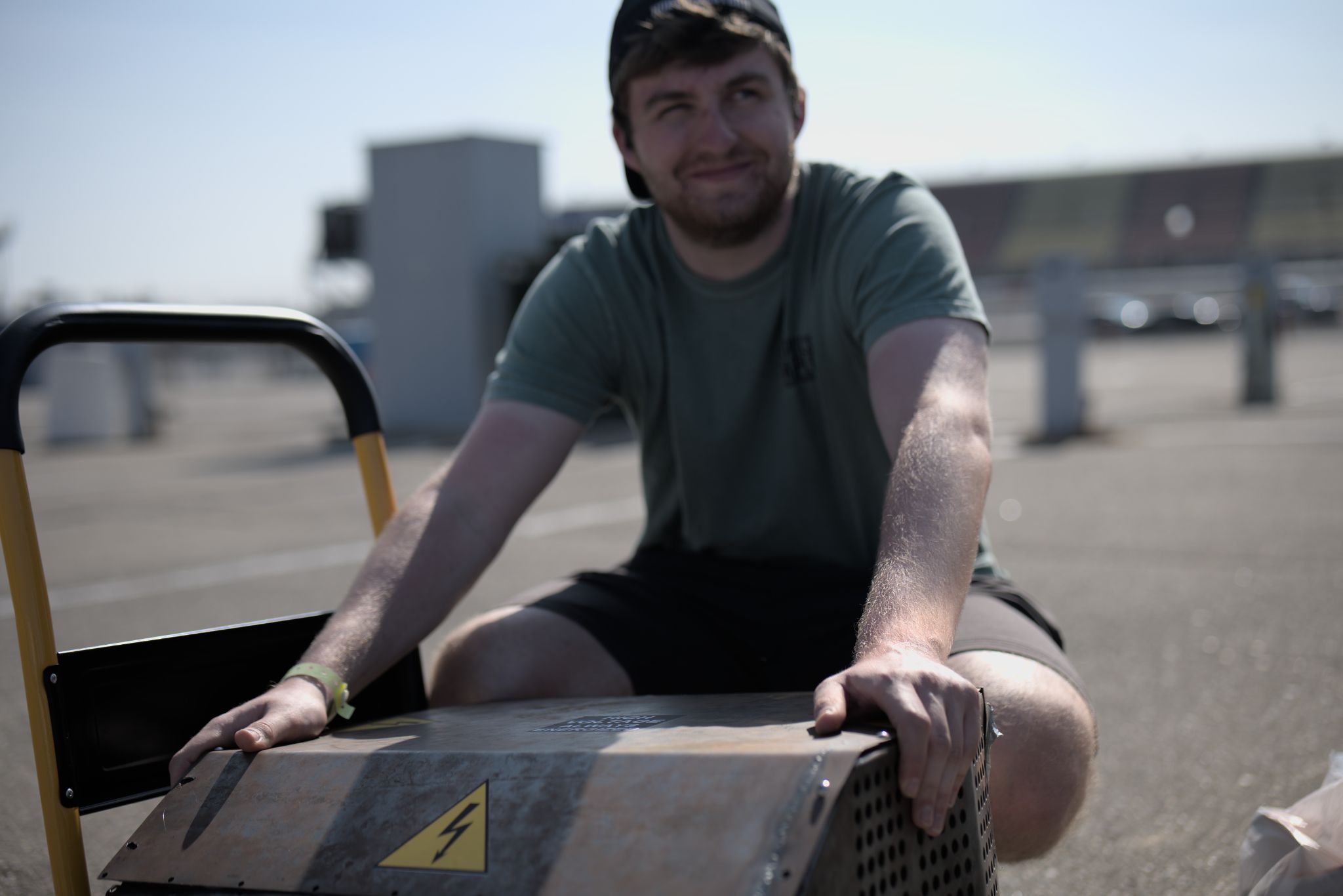
I designed the container for Northwestern Formula Racing’s first electric battery pack (accumulator and battery mean the same thing in FSAE’s rules). It’s the enclosure that holds the high-voltage cells, keeps the driver safe if a cell fails, and electrically isolates the pack from the rest of the car, all while meeting FSAE’s F.10 accumulator container rules on construction, venting, and mounting.
The pack itself, presented alongside the container by the full team (myself, Chloe Leung, Louie Shapiro, and Gabriel Villarroel Narvaez), holds 560 individual cells across 7 segments for 600 volts total, each segment monitored by its own BMS. The container is what all of that lives inside.
Design
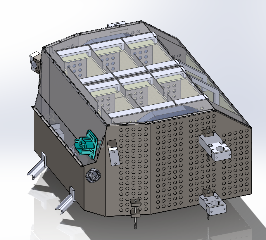
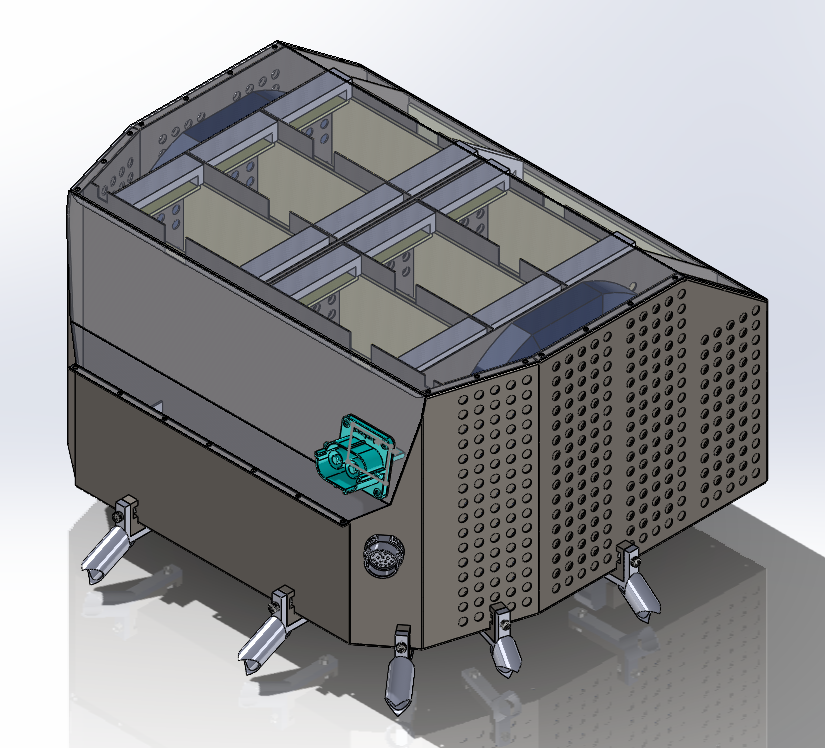
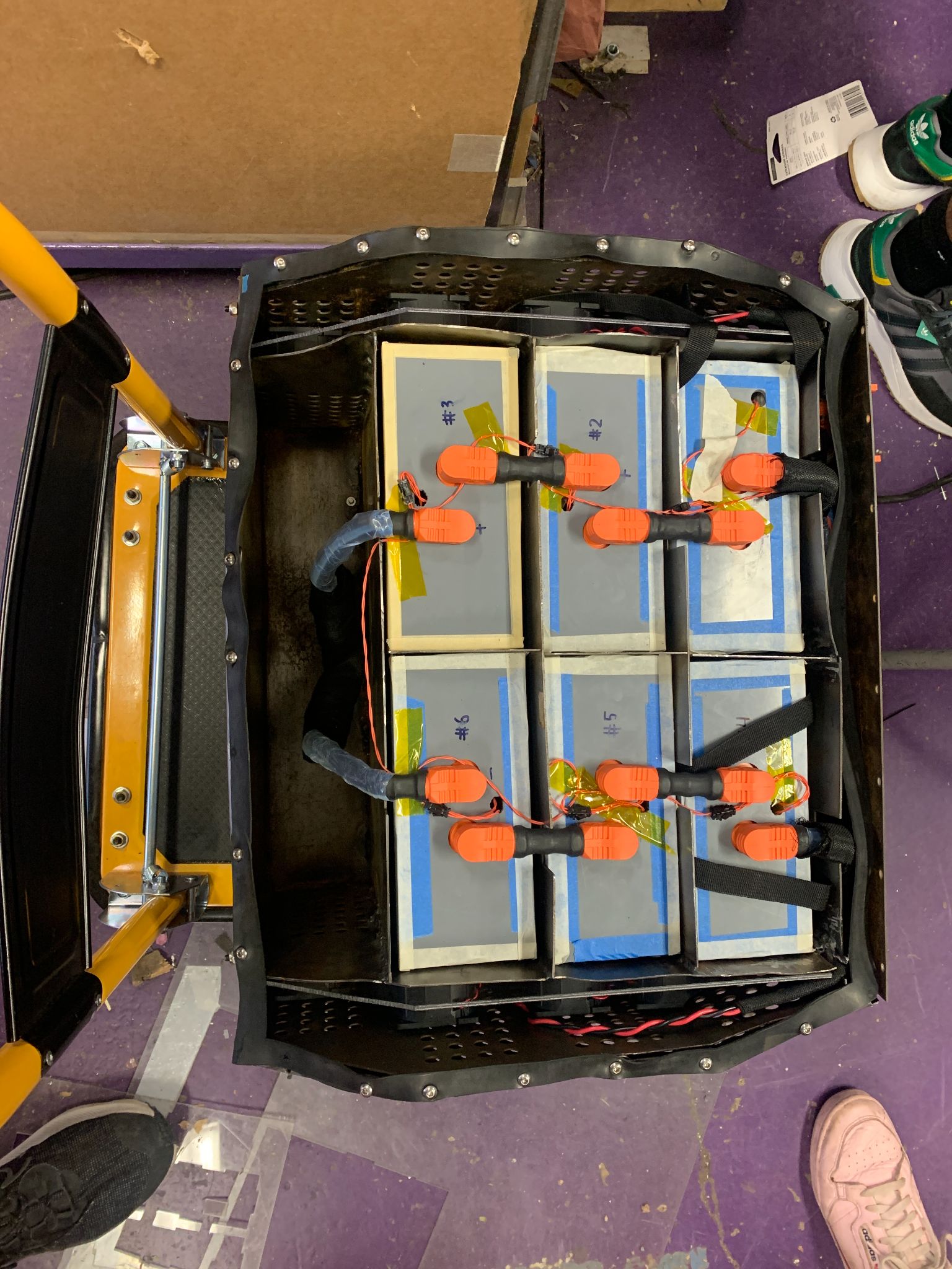
The container splits into 10 sections: six hold 8x10 battery segments, one holds a 4x20 segment, two house the air-cooling fans, and the last holds the high-voltage contactors and BMS boards. I built it from 1.27mm sheet steel, cut on the waterjet and welded, using slots and bends wherever possible to cut down on the number of welds needed.
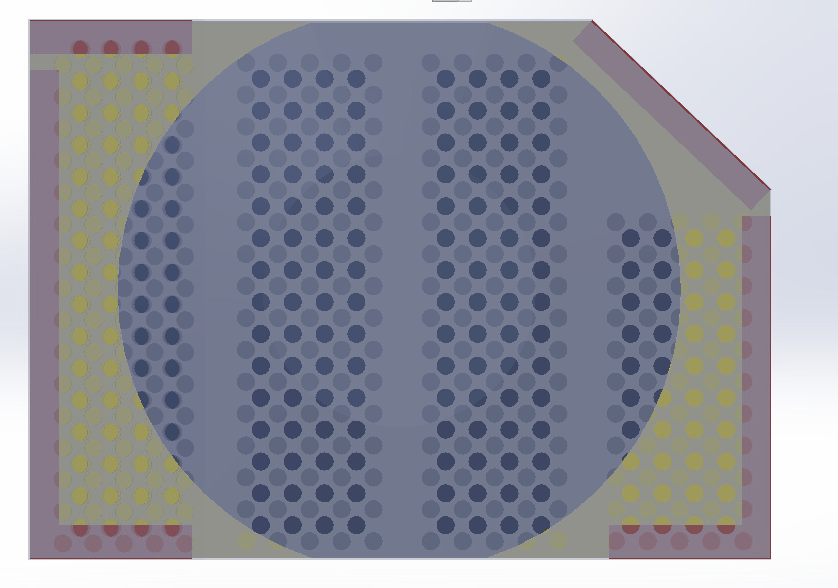
Cooling was one of the trickier constraints. FSAE’s rules don’t allow airflow holes with line of sight to the driver, so the vents had to go on the sides of the car instead, and the whole system still had to keep water out. I mirrored the water-keepout approach from my earlier inverter container project: two layers of offset hole patterns to block high-pressure water, backed by a layer of hydrophobic mesh to catch whatever got through. The final vent pattern uses 10mm holes, square-packed and spaced 17.53mm apart, feeding two 11” 12V fans mounted through a polycarbonate seal and plastic u-channels, with thermistors epoxied directly to the cell terminals to monitor temperature.
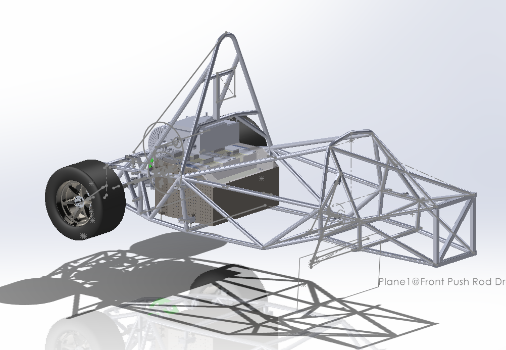
The container is mounted to the frame at 10 points, mostly welded L-brackets that bolt into matching brackets on the frame tubes. Each mount is sized to carry a quarter of the container’s mass at 40G in the horizontal directions and 20G vertical, per FSAE’s load requirements. The lid seals with a rubber gasket, splits into two pieces so the segments are reachable without disconnecting the high-voltage connector, and has bars on its underside to keep the segments from shifting vertically once it’s bolted down.
Iterating around the frame
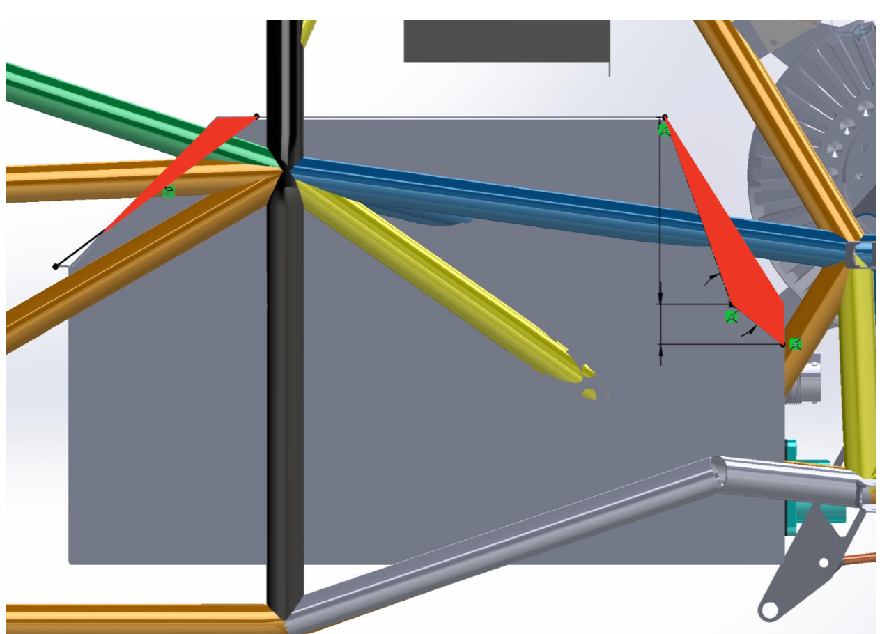
The design went through a full restart partway through. Most of the early work happened on an EV transition subteam with limited communication back to the rest of the team, and once we built a general assembly of the drivetrain, the container didn’t have the mandatory 1” air gap to the frame tubes at the rear of the car. I rebuilt the CAD from scratch with a tapered rear section, keeping each sheet-metal piece as a separate body so it would translate cleanly to flat patterns later. It took several more passes after that just to clear every non-crushable structure in the frame, including a late change once the motor went into the drivetrain assembly and needed its own 1” clearance: the motor moved back and the accumulator moved forward to make room for both.
Manufacturing
Once the geometry was finalized, the sheet steel was cut on the waterjet and bent to shape using the CAD as a reference. The base and the front and back walls are a single piece; the left and right walls form the rest of the exterior.
The design documentation, a diary excerpt from the build, and the team’s final presentation are all linked in the sidebar. The documentation is still a work in progress; a few sections (validation and future work) were never finished.