Robot Design Studio - Power Finger
A tendon-driven finger with a 4-bar linkage that turns into a 5-bar on contact
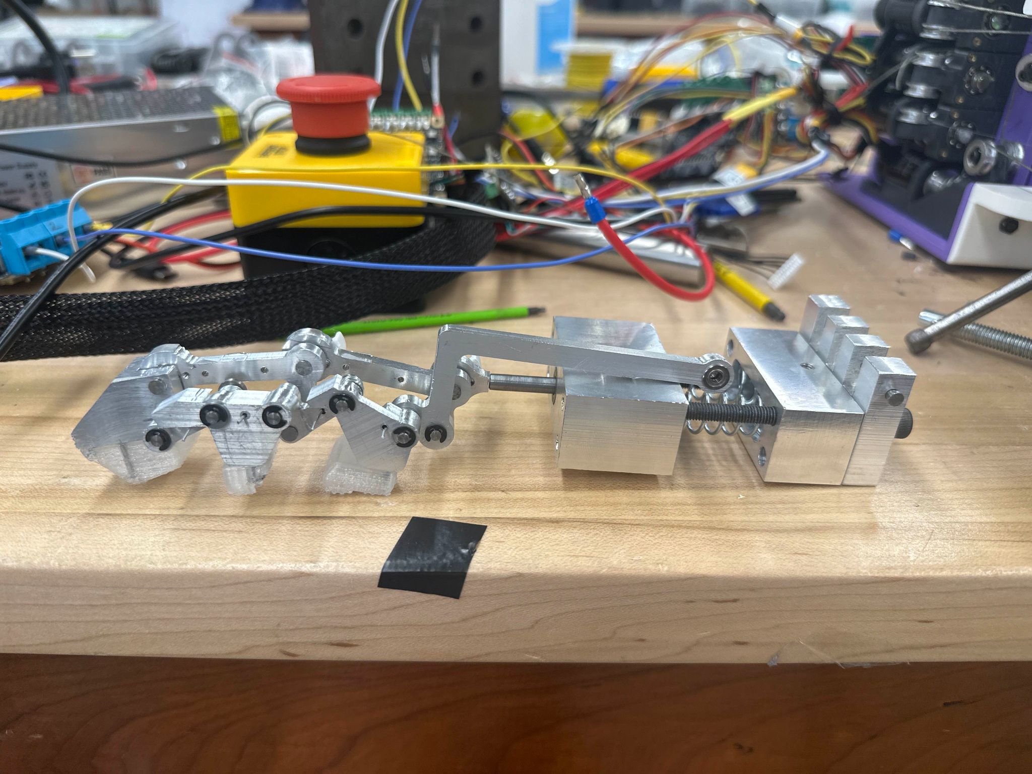
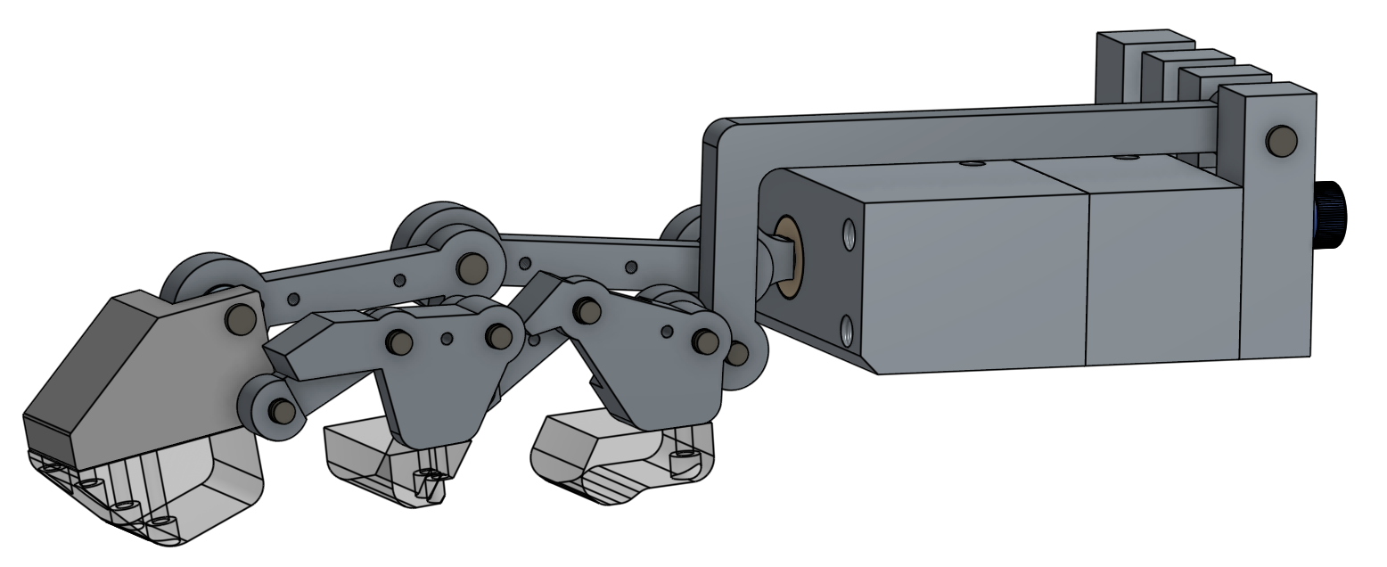
I was responsible for the CAD design and linkages, the CNC manufacturing, and the assembly of this power finger, built alongside the rest of my Capstone group’s work on a full robotic arm. The goal was a mechanically simple finger that could still deliver a strong, adaptive grasp: one active degree of freedom instead of a motor per joint, with the compliance needed for conforming grasps built into the linkage itself rather than added through extra actuators.
Design
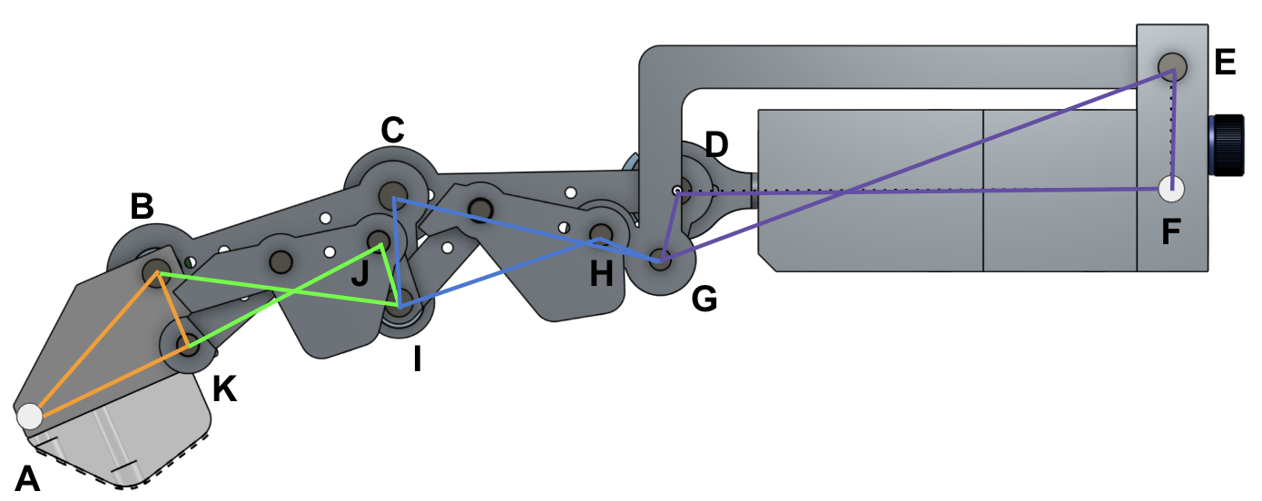
The finger runs on a single tendon-driven degree of freedom with two passive compliant joints. A motor extends a spring through the tendon, which straightens the finger; releasing it lets the spring contract and curl the finger closed. That gives passive grasping, meaning the finger holds its grip with no continuous motor power, and the multi-joint tendon routing provides mechanical advantage, so a relatively small motor force produces a much larger force at the fingertip. The RoboMaster M2006 P36 motor and a 7x19 coated steel tendon (rated to 89N) drive the whole mechanism, producing 10N at the tip fully extended and up to 30N in a full grasp.
The linkage is the interesting part. In free space it behaves as a rigid 4-bar mechanism, tracing a biologically-inspired curl. Once the finger contacts something, reaction forces deflect two of the links, and the mechanism transitions into a 5-bar configuration. That extra degree of freedom is what lets the finger passively wrap around irregular shapes instead of just closing along one fixed path. Sizing the return springs took a few iterations: two springs in parallel gave a preload of 56.92N and a compressed force of 85.51N, chosen to fit the palm’s limited length while still compressing the right amount for the linkage’s range of motion.
Manufacturing
The linkages were originally going to be waterjet cut, but that fell apart for two reasons: several of the linkage features weren’t flat enough for the waterjet to reproduce accurately, and the tolerances came out too loose for how tightly the joints needed to mate. I moved the linkages to CNC milling instead, machined from 6061 aluminum, which meant learning toolpath generation and workholding for small aluminum parts, but it fixed both problems. The pin-joint shafts were turned from steel on a manual lathe for wear resistance under repeated loading, and the extension rod went from an aluminum concept to steel after FEA and early prototypes showed too much deflection under load. The fingertip pads are 0% infill TPU, printed soft on purpose so they conform to whatever they’re gripping.
Testing
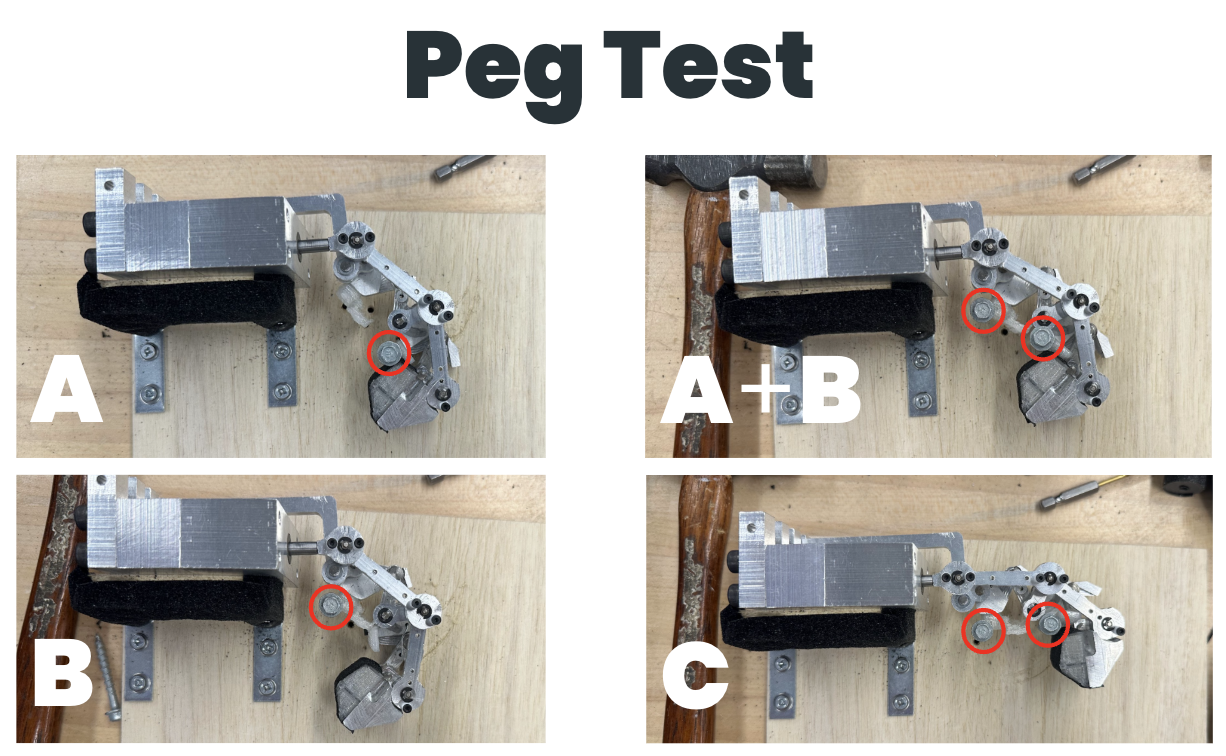
A peg test confirmed the 5-bar linkage’s conforming behavior: pegs placed at different positions around the finger were all gripped without the mechanism binding. A cylinder grasp test measured how much force it took to pull a cylinder out of the finger’s grip across a range of diameters (20mm to 70mm); grasp strength was strongest on smaller objects and dropped off for larger ones, with grip tape helping meaningfully by adding friction.
Reflection
The clearest limitation is that grasp force peaks at full curl and drops off as the finger extends, which limits how consistent the grip is across different grasp positions. Future iterations would target that with different tendon pathing or spring preload, along with a shell to protect the linkages and reduce the cantilever loads a few components currently see. The full mechanical documentation, including the kinematic derivation and Bill of Materials, is linked in the sidebar; it also covers the rest of the hand (wrist, palm, dexterous finger, forearm) built by the rest of the Capstone team.